I recently saw these UI effects in a game called Cult of the Lamb and they were very satisfying to watch. Let’s learn how to create our own types of effects like these.
Prerequisites
- Unity (I’m using 2022.3.17f)
- Photo editing software (Aseprite, Photoshop, etc)
- Seamless perlin noise generator for the noise texture we will need later
Base 2D Shader
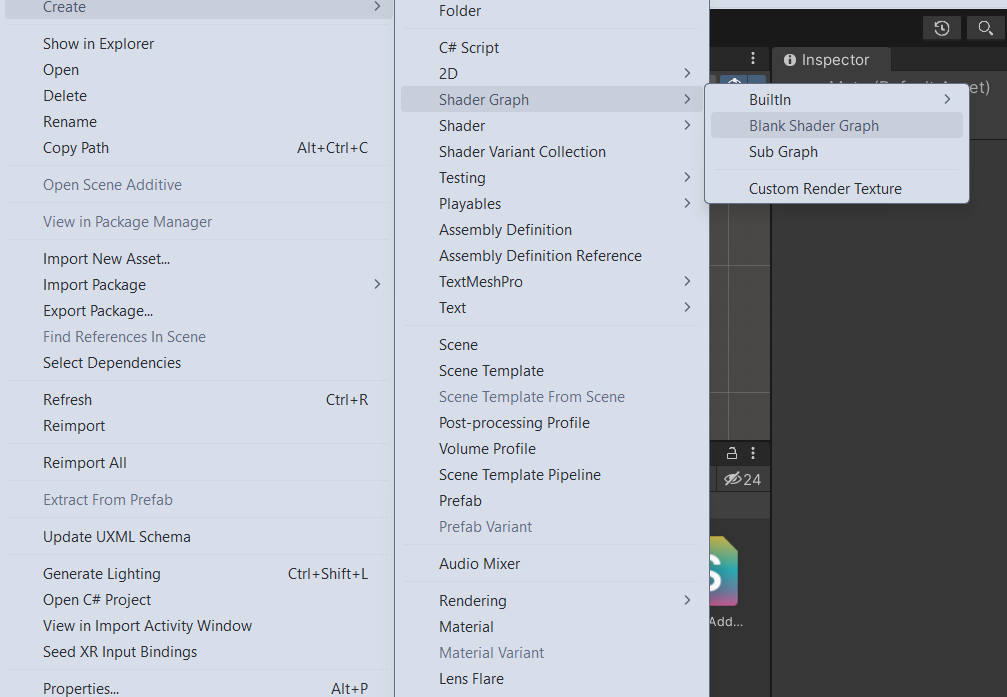
Create a basic empty file with the ‘.shader’ extension in your Unity project or Right click > Shader > Standard Surface Shader
Shader "Custom/EdgeShader"
{
	Properties
	{
	}

	SubShader
	{
		Pass
		{
			CGPROGRAM
			ENDCG
		}
	}
}
We want to begin with a base shader to manipulate, so let’s start by displaying a sprite.
Our shader must expose it to the editor in order to set our texture. Add a line under our properties defining a main texture.
_MainTex ("Base (RGB) Trans (A)", 2D) = "white" {}And the variable under SubShader.
sampler2D _MainTex;
float4 _MainTex_ST;
The _ST value will contain the tiling and offset fields for the material texture properties. This information is passed into our shader in the format we specified.
Now define the vertex and fragment functions.
struct vct
{
	float4 pos : SV_POSITION;
	float2 uv : TEXCOORD0;
};

vct vert_vct (appdata_base v)
{
	vct o;
	o.pos = UnityObjectToClipPos(v.vertex);
	o.uv = TRANSFORM_TEX(v.texcoord, _MainTex);
	return o;
}

fixed4 frag_mult (vct i) : COLOR
{
	fixed4 col = tex2D(_MainTex, i.uv);
	col.rgb = col.rgb * col.a;
	return col;
}
Simple enough.
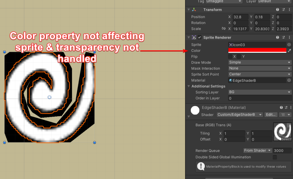
…or is it? That doesn’t look like it’s working properly. Let’s fix it.
We can add a Blend under our tags to fix the transparency issue.
Blend SrcAlpha OneMinusSrcAlphaAnd we can just add the color property to our shader. At this point, we can display 2D sprites on the screen, yay!
Shader "Custom/EdgeShaderB"
{
    Properties
    {
        _MainTex ("Base (RGB) Trans (A)", 2D) = "white" {}
    }

    SubShader
    {
        Tags {"Queue"="Transparent" "IgnoreProjector"="True" "RenderType"="Transparent"}
        Blend SrcAlpha OneMinusSrcAlpha

        Pass
        {
            CGPROGRAM
            #pragma vertex vert_vct
            #pragma fragment frag_mult
            #include "UnityCG.cginc"

            sampler2D _MainTex;
            float4 _MainTex_ST;

            struct vct
            {
                float4 vertex : POSITION;
                fixed4 color : COLOR;
                float2 texcoord : TEXCOORD0;
            };

            vct vert_vct(vct v)
            {
                vct o;
                o.vertex = UnityObjectToClipPos(v.vertex);
                o.color = v.color;
                o.texcoord = v.texcoord;
                return o;
            }

            fixed4 frag_mult (vct i) : COLOR
            {
                fixed4 col = tex2D(_MainTex, i.texcoord) * i.color;
                return col;
            }

            ENDCG
        }
    }
}
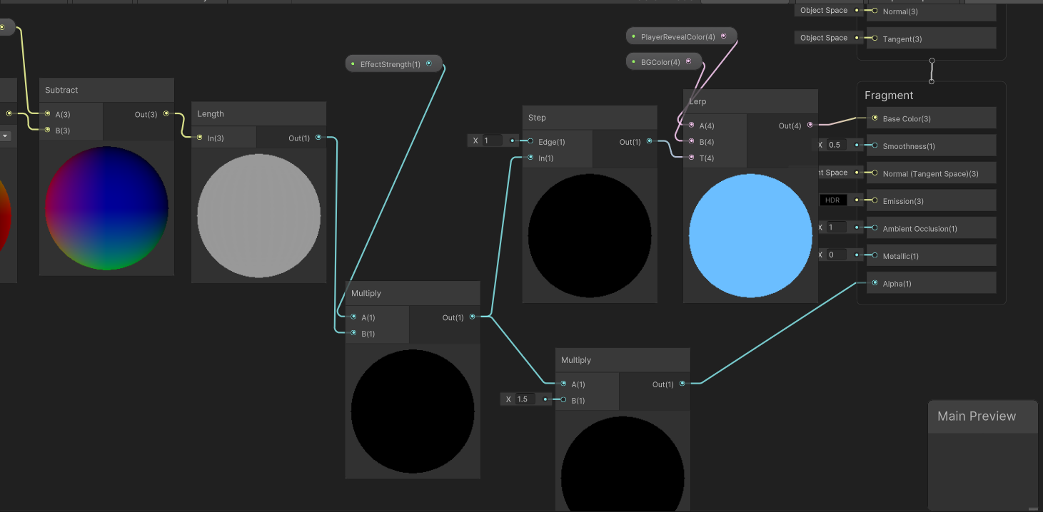
Now we can start messing with things.
Edge Distortion Shader
We want to add some movement and distortion to our sprite. Begin with movement.
How can we manipulate our shader pixels? Let’s show an example by modifying our main texture. We’ll simply change the position. To do so, we can do something simple like shifting the texture coordinate down and to the left.
fixed4 frag_mult (vct i) : COLOR
{
	float2 shift = i.texcoord + float2(0.15, 0.25);
	fixed4 col = tex2D(_MainTex, shift) * i.color;

	return col;
}
Okay, now how about some movement?
fixed4 frag_mult (vct i) : COLOR
{
	float2 shift = i.texcoord + float2(cos(_Time.x * 2.0) * 0.2, sin(_Time.x * 2.0) * 0.2);
	fixed4 col = tex2D(_MainTex, shift) * i.color;

	return col;
}
If you examine your sprite at this point, you may notice some odd distortion as it moves.
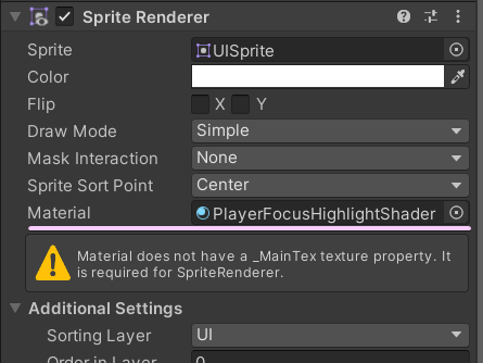
Set your sprite’s import settings correctly!
Mesh Type: Full Rect
Wrap Mode: Repeat
Once you ensure your sprite has the correct import settings, it’s time to introduce our final 2d sprite we want to manipulate with the shader to achieve our effect.
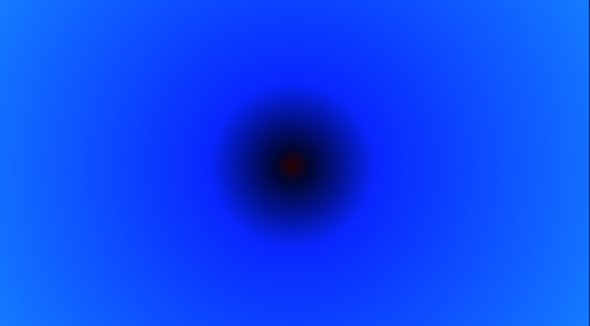
This image will greatly change the shader appearance, and you should try different gradients and patterns. Here’s my image scaled up:
But I recommend using the smallest resolution that looks good for your project due to memory and performance.
We also need a seamless noise texture, for the distortion.
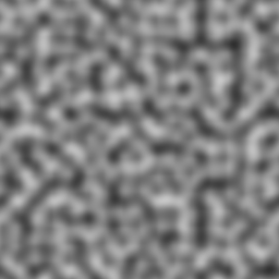
Let’s add another variable for it.
_NoiseTex ("Base (RGB) Trans (A)", 2D) = "white" {}Once we’ve assigned our noise texture, it’s time to start moving it.
fixed4 frag_mult (vct i) : COLOR
{
float2 shim = i.texcoord + float2(
tex2D(_NoiseTex, i.vertex.xy/500 - float2(_Time.w/60, 0)).x,
tex2D(_NoiseTex, i.vertex.xy/500 - float2(0, _Time.w/60)).y
);
fixed4 col = tex2D(_MainTex, shim) * i.color;
return col;
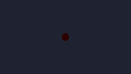
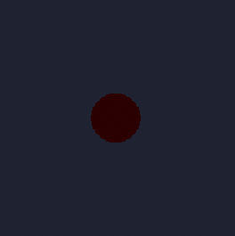
}Now, add the static sprite to its left in the same color and connect it vertically.
Adjusting the transparency will function as expected, so we could overlay this.
Shader "Custom/EdgeShader"
{
    Properties
    {
        _MainTex ("Base (RGB) Trans (A)", 2D) = "white" {}
        _NoiseTex ("Base (RGB) Trans (A)", 2D) = "white" {}
    }

    SubShader
    {
        Tags {"Queue"="Transparent" "IgnoreProjector"="True" "RenderType"="Transparent"}
        Blend SrcAlpha OneMinusSrcAlpha

        Pass
        {
            CGPROGRAM
            #pragma vertex vert_vct
            #pragma fragment frag_mult
            #include "UnityCG.cginc"

            sampler2D _MainTex;
            sampler2D _NoiseTex;
            float4 _MainTex_ST;
            float4 _NoiseTex_ST;

            struct vct
            {
                float4 vertex : POSITION;
                fixed4 color : COLOR;
                float2 texcoord : TEXCOORD0;
            };

            vct vert_vct(vct v)
            {
                vct o;
                o.vertex = UnityObjectToClipPos(v.vertex);
                o.color = v.color;
                o.texcoord = v.texcoord;
                return o;
            }

            fixed4 frag_mult (vct i) : COLOR
            {
                    float2 shim = i.texcoord +
                float2(tex2D(_NoiseTex, i.vertex.xy/500 - float2(_Time.w/60, 0)).x,
                tex2D(_NoiseTex, i.vertex.xy/500 - float2(0, _Time.w/60)).y);
                fixed4 col = tex2D(_MainTex, shim) * i.color;
                return col;
            }

            ENDCG
        }
    }
}
Crown Shader
Here’s my quick little crown sprite.

Let’s make it evil.
We can repurpose the wall shader we just created and scale down the distortion as well as smoothing it
fixed4 frag_mult(v2f_vct i) : COLOR
{
    float2 shim = i.texcoord + float2(
        tex2D(_NoiseTex, i.vertex.xy/250 - float2(_Time.w/7.2, 0)).x,
        tex2D(_NoiseTex, i.vertex.xy/250 - float2(0, _Time.w/7.2)).y
    )/ 20;

    fixed4 col = tex2D(_MainTex, col) * i.color;

    return col;
}
Then we can add another pass to handle the normal sprite display.
Shader "Custom/CrownShader"
{
    Properties
    {
        _MainTex ("Base (RGB) Trans (A)", 2D) = "white" {}
        _NoiseTex ("Base (RGB) Trans (A)", 2D) = "white" {}
        _SpriteColor ("Color Tint Mult", Color) = (1,1,1,1)
    }

    SubShader
    {
        Tags {"Queue"="Transparent" "IgnoreProjector"="True" "RenderType"="Transparent"}
        Blend SrcAlpha OneMinusSrcAlpha

        Pass
        {
            CGPROGRAM
            #pragma vertex vert_vct
            #pragma fragment frag_mult
            #pragma fragmentoption ARB_precision_hint_fastest
            #include "UnityCG.cginc"

            sampler2D _MainTex;
            sampler2D _NoiseTex;
            float4 _MainTex_ST;
            float4 _NoiseTex_ST;

            struct vct
            {
                float4 vertex : POSITION;
                float4 color : COLOR;
                float2 texcoord : TEXCOORD0;
            };

            vct vert_vct(vct v)
            {
                vct o;
                o.vertex = UnityObjectToClipPos(v.vertex);
                o.color = v.color;
                o.texcoord = v.texcoord;
                return o;
            }

            fixed4 frag_mult(vct i) : COLOR
            {
                float2 shim = i.texcoord + float2(
                    tex2D(_NoiseTex, i.vertex.xy/250 - float2(_Time.w/7.2, 0)).x,
                    tex2D(_NoiseTex, i.vertex.xy/250 - float2(0, _Time.w/7.2)).y
                )/ 20;

                shim *= float2(0.97, 0.91);
                shim -= float2(0.01, 0);

                fixed4 col = tex2D(_MainTex, shim) * i.color;
                return col;
            }

            ENDCG
        }
        Pass
        {
            CGPROGRAM
            #pragma vertex vert_vct
            #pragma fragment frag_mult
            #pragma fragmentoption ARB_precision_hint_fastest
            #include "UnityCG.cginc"

            sampler2D _MainTex;
            sampler2D _NoiseTex;
            float4 _MainTex_ST;
            float4 _NoiseTex_ST;

            float4 _SpriteColor;

            struct vct
            {
                float4 vertex : POSITION;
                float4 color : COLOR;
                float2 texcoord : TEXCOORD0;
            };

            vct vert_vct(vct v)
            {
                vct o;
                o.vertex = UnityObjectToClipPos(v.vertex);
                o.color = v.color;
                o.texcoord = v.texcoord;
                return o;
            }

            fixed4 frag_mult(vct i) : COLOR
            {
                float2 uv = i.texcoord;
                uv -= 0.5;
                uv *= 1.1;
                uv += 0.5;

                fixed4 col = tex2D(_MainTex, uv);
                col.rgb = _SpriteColor.rgb;

                return col;
            }

            ENDCG
        }
    }
}
It helps me if you share this post
https://rose.dev/blog/2024/01/26/unity-shaders-intro-part-2-hlsl-cg-creating-cult-of-the-lamb-like-ui-distortion-effects/
Published 2024-01-26 06:00:00